
(EN) 4-RECEIVER
V)-ACTION DESIGN.
CONCEPTION OF SINGLE SHOT MATCH ACTIONS
4-RECEIVER.
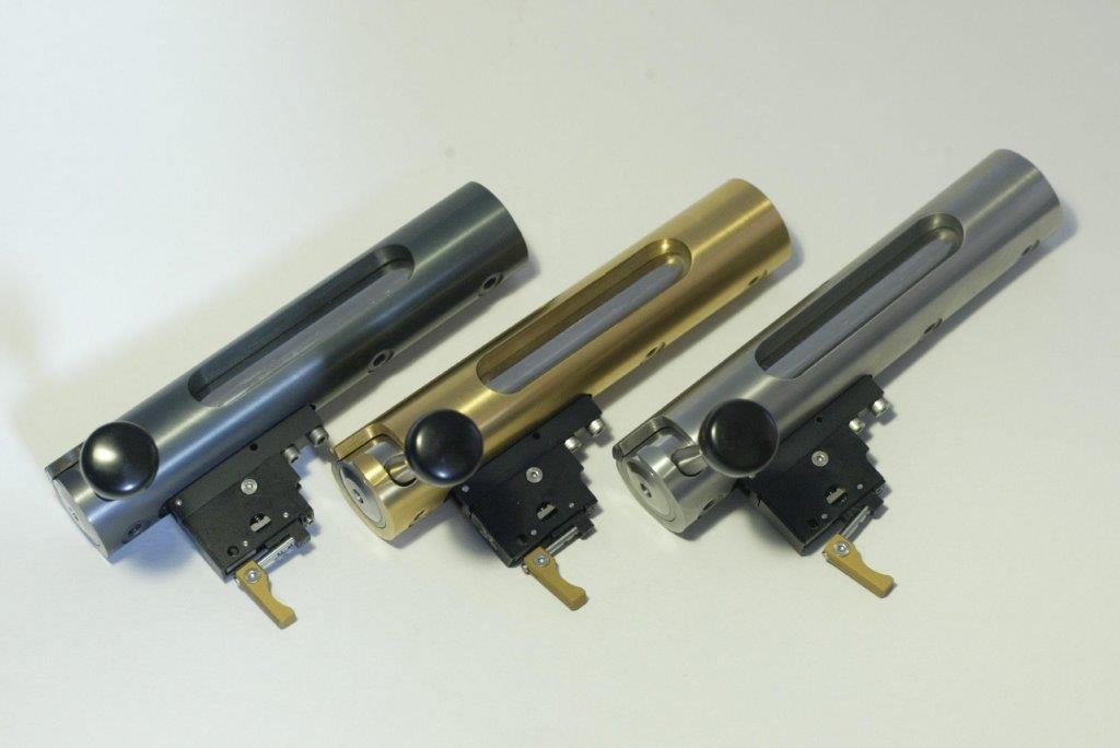
The RECEIVER is just quite a little more than what its name implies..
The first point to consider is STIFFNESS. With modern long and heavy barrels, the receiver must be rigid to withstand the long cantilevered barrels weights. The receiver must also present an important bearing surface on the bedding, and necessarily 3 bedding screws, with the rear one placed as far as possible at the rear to better balance the barrel weight.. Rear bedding screw placed amidships ahead of the trigger might be (and are) an option for smallbore actions, but NOT for full-sized centrefires.
Also, should the receiver be designed with a ‘tanged’ rear shape, this tang must be stiff enough to not flex, a common defect on some lightened or ‘streamlined’ repeater receivers. Ideal for our match single shot receivers being the plain tubular shape. Single shot actions purposely designed have no tang.
To be stiff, a receiver must:
---Be of sufficient diameter to ensure sufficient cross sections all the way long. This also helps to balance the barrel weight.
---Have a large ring at front to ensure strong hold of the barrel and a shank of sufficient diameter and length to ensure the said hold.
--- Have the necessary functional openings as reduced in cross section as possible.
---The old 1.0625 (26,98mm) barrel shank diameter looks to be the minimal admissible diameter to ensure the heavy barrel hold, and also in view of the magnum chambers now popular, the barrel shank is preferably to be 1.125’ (28,58mm). This implies also a slight increase in receiver diameter in order to both maintaining the rifle balance, and ensure also sufficiently long internal bedding screws female threads . 38mm (1.496’) outside diameter allow both increased diameter barrel shank and sufficient bedding screws tapping length.
Recoil is to be taken by either a spigot screwed in one of the recessed bedding screws holes (the middle one), or, most ideally by the perpendicular rear face of the tubular receiver, this being also the ideal solution if the action is to be fitted in a tube stock as it seem to be an actual trend.
I would never consider the recoil lug screwed between barrel shoulder and action face…If there was to be a front recoil lug, this should be integral machined in the receiver. In fact, I think the front separate recoil lug, even if indexed, generates more issues than it resolves (double the number of barrel/receiver bearing surfaces, barrel swap problems, integration in tube stocks….).
The receiver functions are multiple and need to be studied separately and as a whole. Receiver is the core of multiple functions:
Key words here are ;Concentricity, Alignment, Squareness , Timings, Close Tolerances and Functionality .
---Concentricity is to be maintained, not only between the various borings, but also with the outside diameter, an important but challenging factor for front-locking actions as the bolt raceway is bored from the rear and the stepped bores and threads at the front have to be made both ways: barrel threads and receiver counter-lugs recess from the front, and lugs throat and bolt raceway from the rear and, in this case of double operation, it is the outside diameter who serves as the only reference for maintaining front and rear bores concentricity.
This problem of internal/external concentricity is of less concern for actions with rear lugs system, in which all the borings are stepped down from the front to the rear, and all borings performed from front in one single operation, making them absolutely concentric and aligned, with also perfectly squared front face and lugs bearing shoulder.
---Close tolerances :Bolt and receiver have to be made on close fitting tolerances. The main point being concentricity and close fit at lugs level for front locking actions. Effectively, the close fit at lugs level is difficult to realise with 2 lugs designs, and this makes the centering of the bolt starting further backwards by its body in the receiver bore starting some 25mm (1’) rear of the cartridge head. This is less of a problem for 3 lugs actions, providing the bolt 3 points lugs apexes front centering is correctly realised to tight fit in the corresponding bore of the receiver (not always the case as too often neglected…), and the problem is non-existent with rear locking, in which the cylindrical bolthead fits perfectly from the front, exactly where it is important: at case head recess level.
---Functionality: the receiver has also to perform multiple static functions:
--A- Be an interface
with the stock and withstand recoil.
The interface with the stock is ensured by screws clamping the Receiver bottom surface against the Bedding system, conventional bedding, on pillars or not, or bedding block of various principles (plain Vee Blocks, fleXibloc..).
The design must allow for large bedding bearing surface with no protrusion other than eventually an integrated recoil lug, although it is always better to plan for a detachable or non-protruding (such as a spigot screwed into the middle bedding screw countersink hole) or better the rear face of the Receiver), rendering the action suitable for any recoil absorption system, including direct integration in Tube stocks.
The room made available underneath by the absence of a magazine well allow for 3 Bedding screws, ideally 2 ahead of the trigger and one behind.
Placing the 3 screws ahead of the trigger does not allow even bearing pressure of the receiver in the bedding or block. Actions with no bedding screw at the rear behind the trigger are reputed to be very sensitive to correct screws torqueing.
Usually, bedding screws are either UNF1/4x28, M6x1,00 or M6x0,75, with the 1/4x28 UNF becoming the norm as it represent all the advantages: larger threads core section of the screw, fine threads and availability. Fine threads allow reduce tightening torques.
---B- Holds the sights.
Provision is to be made for possible fitting of :
--Side mounting for some LR rearsights, using an aftermarket or OEM bracket.
--Anschuetz-type dovetail for top-mounting of Long Range or ISSF sights.
--Scope mounting screw holes in two groups at front and rear. For more strength and positioning capability, 3 screws at front where the screws are at more shear risk, spaced in groups at a standard spacing, for instance .860’ (21,85mm), .600’ (15,24mm) or .500’(12,70mm), the .860 being the common.
---C- Holds and center
the barrel.
First is to determine Shank diameter. On common shank diameter offer is either 1.0625’ (26,99mm) or 1.125 (28,58mm), the later highly recommendable for magnum calibers..
Barrel shank thread pitches available are either 16 ,18 , and in some cases,20tpi. The standard dimensions allow to have them realised under close standardized tolerances and be controlled by use of threads plug gauges.
As threads assemblies are never fully self-centering, it is felt necessary to have a centering diameter at front, or better at front and rear of the shank threads, should the shank lenght allow, of which the close diametral tolerances fit makes the matching diameters of the barrel perfectly centering it In the receiver. This is the most efficient array for barrel swapping without zero shift. This is a C.G standard since long.
Front face of the receiver being perfectly square with the threaded section and all bores ensure a perfect fit. Ideally, a double shoulder faces bearing, at front against the barrel shank shoulder and its rear face against the internal collar in the receiver perfect the fit and make barrel switch easy. Only very close length tolerances machining allow this. This is also a C.G standard concept.
---D- Holds, ensure guidance, centering, bolting and maintain of the Bolt.
This is one of the most important points to consider in an action design.
--Guidance implies close dimensional tolerances and straightness. Allowance for subsequent treatments (platings, coatings) have to be calculated in function of the process requirements (coat thickness).
--Concentricity have already been developed, and need no further mention of its importance.
--Bolting: geometry and operation of the functions of bolting, camming and cocking are to be determined , with each one influencing the other. All angles, cams, ramps need a perfect timing at close angular tolerances. Necessary clearances are to be determined to the minimal admissible in order to not impair the cycling.
---E-Ensure recocking
of the firing mechanism.
The principle of recocking consist in preventing the rotation of the firing pin system when opening and closing the Bolt. This is ensured in two possible ways:
--1) A sear guide slot is necessary to ensure recocking by action for the sear on the cocking ramp. Hard receiver material at this point is necessary to prevent long term wear and ensure reduced friction.
--2) A Shroud bearing against a surface of the receiver is prevented in rotation when opening/closing the Bolt. This method is little employed in Match single shot actions as, situated at the rear of the Bolt, it makes the mechanism longer and consequently the Firing Pin heavier.
---F-Provide a ramp to ensure primary extraction
This is a surface machined in either helicoidal or radiused shape on which a cam machined on the Bolt comes to bear at the end of the Bolt lift movement to force the Bolt to move backwards a small amount to ensure the extraction of the slightly stuck fired case.
Primary extraction should not have LESS than 1,5mm (.060’) of rearward movement, 2mm (.080’) being the design objective. It is also interlinked with the Lugs engagement camming shape. C.Gs have 2mm primary extraction.
---G-Holds the trigger
.
The trigger must be correctly positioned vertically to ensure the designed Sear engagement and lenghtwise to ensure the correct timing and designed FP travel.
The trigger can be fixed by:
--One single screw at front. This is not a good fixing, as a single screw get loose easily and, the screw being situated far ahead of the Sear cocking point, there is possible variations in Sear engagement who can occur in relation with the tightening of the screw.
--TWO screws at front and at rear. The optimal solution as it ensures good hold, easy removal and precise and constant Sear/Trigger engagement..
--The double crosspins system (Remington) maintains a precise and constant Sear engagement and timing. The number of aftermarkets available on this system makes a trigger for every taste and shooting conditions.
The 2 crosspins system as it is originally makes removal difficult, but itcan be adapted from the action concept for easy removal combination of crosspins and screws.
This crosspin fitting is very accurate and safe, but does not allow lenghtwise position adjustment.
To date, except certain concept constraints, planning a custom action not suited for the crosspins Remington trigger fitting,would bean error..
R.G.C
Inscrivez-vous au blog
Soyez prévenu par email des prochaines mises à jour
Rejoignez les 85 autres membres